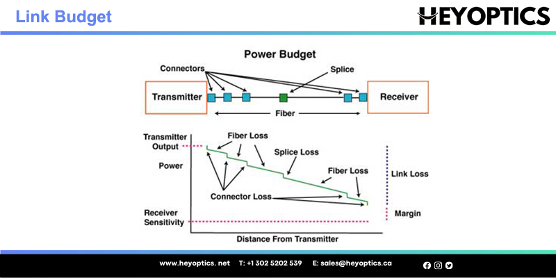
How to Calculate the Fiber Link Budget?
Design of a fiber optic system is a balancing act. As with any system, you need to set criteria for performance and then determine how to meet those criteria. It’s important to remember that we are talking about a system that is the sum of its parts. The fiber link budget is key to a fiber optic system, it refers to the amount of loss that a fiber cable plant should have. This paper will explain how to determine fiber link budget.
There are a number of ways to tackle the problem of determining the link budget for a particular fiber optic link system. The easiest and most accurate way is to perform an Optical Time Domain Reflectometer (OTDR) trace of the actual fiber link. This will give you the actual loss values for all events (connectors, splices and fiber loss) in the link. In the absence of an actual OTDR trace, there are two alternatives that can be used to estimate the link budget.
- Estimate the total link loss across an existing fiber optic link in the fiber length and loss variables are known
- Estimate the maximum fiber distance if the optical budget and loss variable are known.
Calculation of a fiber optic system link budget is based upon a long list of elements. Following is a list of basic items used to determine general transmission system performance:
- Fiber Loss Factor – Fiber loss generally has the greatest impact on overall system performance. The fiber strand manufacturer provides a loss factor in terms of dB per kilometer. A total fiber loss calculation is made based on the distance x the loss factor. Distance, in this case, the total length of the fiber cable, not just the map distance.
- Type of fiber – Most single-mode fibers have a loss factor of between 0.25 (@ 1550nm) and 0.35 (@ 1310nm) dB/km. Multimode fibers have a loss factor of about 2.5 (@ 850nm) and 0.8 (@ 1300nm) dB/km. The type of fiber used is very important. Multimode fibers are used with LED transmitters which generally don’t have enough power to travel more than 1km. Single mode fibers are used with LASER transmitters like DFB, FP that come in various power outputs for “long reach” or “short reach” criteria.
- Transmitter – There is two basic type of transmitters used in fiber optic systems. LASER which comes in three varieties: high, medium, and low (long reach, medium reach and short reach). Overall system design will determine which type is used. LED transmitters are used with multimode fibers, however, there is a “high power” LED which can be used with Single-mode fiber. Transmitters are rated in terms of light output at the connector, such as -5dB. A transmitter is typically referred to as an “emitter”.
- Receiver Sensitivity – The ability of a fiber optic receiver to see a light source. A receiving device needs a certain minimum amount of received light to function within specification. Receivers are rated in terms of the required minimum level of received light such as -27dB. A receiver is also referred to as a “detector”.
- Number and type of splices – There are two types of splices. Mechanical, which use a set of connectors on the ends of the fibers, and fusion, which is a physical direct mating of the fiber ends. Mechanical splice loss is generally calculated in a range of 0.7 to 1.5 dB per connector. Fusion splices are calculated at between 0.1 and 0.5 dB per splice. Because of their limited loss factor, fusion splices are preferred.
- Margin – This is an important factor. A system can’t be designed based on simply reaching a receiver with the minimum amount of required light. The light power budget margin accounts for the aging of the fiber, aging of the transmitter and receiver components, the addition of devices along the cable path, incidental twisting and bending of the fiber cable, additional splices to repair cable breaks, etc. Most system designers will add a loss budget margin of 3dB to 10dB.
The following table includes commonly accepted loss values in these calculations:
| Fiber Type | Wavelength | Fiber attenuation/ km | ConnectorLoss | Splice Loss |
| Multimode 50/150μm | 850 nm1310 nm | 2.5 dB0.8 dB | 0.75 dB0.75 dB | 0.1 dB |
| Multimode 62.5/125μm | 850 nm1310 nm | 3.0dB0.7 dB | 0.75 dB0.75 dB | 0.1 dB |
| Single Mode 9μm | 1310 nm | 0.35 dB | 0.75 dB | 0.1 dB |
| Single Mode 9μm | 1550 nm | 0.22 dB | 0.75 dB | 0.1 dB |
Link Budget = [fiber length (km) × fiber attenuation per km] + [splice loss × # of splices]+[connector loss × # of connectors] + [safety margin] For example: Assume a 10 km single mode fiber link at 1310nm with 2 connector pairs and 2 splices.
Link Budget= [10km × 0.35dB/km] + [0.1dB × 2] + [0.75dB × 2] + [3.0dB] = 8.2dB
In this example, an estimated 8.2dB of power would be required to transmit across this link. Of course, it is very important to measure and verify the actual link loss values once the link is established to identify any potential performance issues.
Calculating Cable Plant Link Loss Budget
Loss budget analysis is the calculation of a fiber optic cabling system's estimated loss performance characteristics. This is sometimes confused with the communication system "power budget" which is a specification of the dynamic range of the electronics, the difference between the output power of the transmitter coupled into the fiber and the minimum received power required at the receiver for proper data transmission. The communications system power budget will set a limit for the loss of the cable plant.
The cable plant loss budget needs to consider transceiver wavelength, fiber type, and link length plus the losses incurred in splices, connections and other passive devices like FTTH or OLAN PON splitters. Attenuation and bandwidth/dispersion are the key parameters for the cable plant loss budget analysis.
FOA has a online Loss Budget Calculator web page that will calculate the loss budget for your cable plant. This is a good page to bookmark on your smartphone, tablet and/or laptop to have for making calculations in the field.
FOA Loss Budget App
FOA has a free app for iOS smartphones and tablets that will calculate loss budgets for the cable plant you are designing or testing. See the app store for your device for details.
Estimate Fiber Distance
This calculation will estimate the maximum distance of a particular fiber optic link given the optical link budget and the number of connectors and splices contained in the link:
Fiber length = ([Optical budget] – [Link Budget]) / [fiber loss/km] Fiber length = {[(min. TX PWR) – (RX sensitivity)]- [splice loss × # of splices]- [connector loss × # of connectors]- [safety margin]}÷ [fiber lost/km] For example: Assume a Gigabit Ethernet SFP module (PN: OSP1250-3120DCR) Single mode link at 1310nm with 2 connector pairs and 2 splices:
Fiber length = {[(-9.0dB) – (-21.0dB)] – [0.1dB × 2] – [0.75dB × 2] – [3.0dB]} / [0.35dB/km] = 20.8km.In this example, an estimated 20.8 km distance is possible before dissipating the optical power to a value below the Rx sensitivity. As always, it is very important to measure and verify the actual link loss values once the link is established to identify potential performance issues. Actual maximum distances will be vary depending on:
- Actual optical fiber attenuation per km
- Optical fiber design and age
- Quality of connectors and actual loss per pair
- Quality of splices and actual loss per splice
- The number of splices and connectors in the link