Know About Digital Diagnostic Monitoring Function in Ethernet Switches
DDM or Digital Diagnostic Monitoring is a technology that allows testing the function of a device in real-time. In the market, you get devices with or, without DDM. But, opting for DDM-enabled electronic and network devices such as Ethernet switches is always a good option because of the benefits this technology offers. It is always wide to make informed decisions, especially when you need to invest in technology and networking. Also, DDM-enabled devices generate alert messages if there are changes in their functions or set parameters. So, it is worth spending that extra money and buying an Ethernet switch with the DDM function.
What Is Digital Diagnostic Monitoring (DDM)?
“D” in GLC-SX-MMD represents the DDM function which is short for digital diagnostic monitoring according to the industry standard MSA (Multi-Source Agreement) SFF-8472 and is also known as DOM (Digital Optical Monitoring). When buying a fiber optic transceiver today, you will have the option with or without DDM/DOM. And most of the modern transceivers are with the DDM function. This technology allows the user to monitor real-time parameters of the fiber optic transceivers, like optical input/output power, temperature, laser bias current, transceiver supply voltage, etc.
What is an Ethernet Switch and How Does it Function?
An Ethernet switch is an important connectivity device that acts as a central hub in a wired network. Also known as a network switch, its ports are connected to computers, cameras, printers, and other devices on a private network. You can connect to the Internet by connecting this Ethernet switch to a router with the help of a cable. So, it serves a purpose in private or business networks as well as established Internet connectivity as and how required. In short, it acts as a central communication interface for all the connected devices on the network, which transfer data packets from one LAN port to another. Each Ethernet device has a unique ID depending on the manufacturer. Switches use this to identify connectivity between devices. It creates a sort of database to help map the source and destination addresses for data packets to be delivered rightly. You get a combination of a router and switch as a single device. Also, you can connect multiple Ethernet switches to form a large network.
What Can Digital Diagnostic Monitoring Do?
DDM function can provide component monitoring on transceiver applications in detail. However, DDM’s application is not limited to this. The SFF-8472 added the DDM interface and outlined that the DDM interface is an extension of the serial ID interface defined in GBIC specification, as well as the SFP MSA. DDM interface includes a system of alarm and warning flags which alert the host system when particular operating parameters are outside of a factory set normal operating. Thus, the DDM interface can also enable the end user with the capabilities of fault isolation and failure prediction. This part is to illustrate what can be done with DDM.
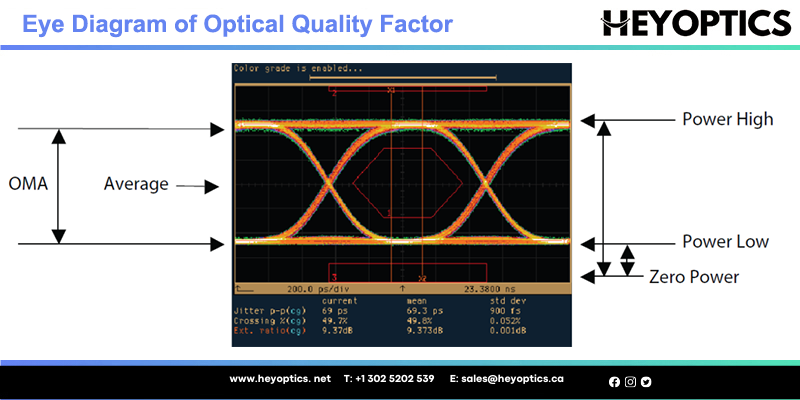
Component Monitoring: The DDM enables the end user to monitor key parameters in the performance of the fiber optic transceiver including the following:
- Transceiver temperature
- Transceiver supply voltage
- Laser bias current
- Transmit average optical power
- Received optical modulation amplitude (OMA) or Average Optical Power
The real-time diagnostic parameters can be monitored to alert the system when the transceiver’s specified operating limits are exceeded and compliance cannot be ensured. The following picture shows the eye diagram illustrating optical figures of merit.
Fault isolation: The DDM function can be used to isolate the particular location of the fault in a fiber optic network system. Combining the DDM interface status flags, transceiver hard pins, and diagnostic parametric monitor data, the specific location and cause of a link failure can be pinpointed.
Failure prediction: The DDM can also be used to help in failure prediction on fiber optic links, which is based on the transceiver parametric performance. Although, this application is not yet fully mature, there is still room for improvement. Two basic types of failure conditions can be seen on fiber optic transceivers:
- Device faults—A device non-operation or malfunction. Typically applied more to transmitter performance, due to the nature of semiconductor lasers.
- High error rate conditions—Operating conditions are such that the transceiver is operating at its signal-to-noise limit. Applies more to fiber optic receiver performance.
Providing parameter monitoring, fault isolation, and failure prediction, fiber optic transceivers with DDM help to ensure that the business can be proactive in preventative maintenance of the network and ensure business continuity. And it would be easy to explain why modern transceivers are with DDM and why GLC-SX-MMD can replace GLC-SX-MM. It is an irresistible development trend in industry and technology.
Use of Digital Diagnostic Monitoring in Ethernet Switches
Ethernet switches are used as a connectivity interface in much real time and mission-critical applications. So, it is crucial that they provide the right output at the right time. Some of the applications of Ethernet switches include traffic control systems and stop lights on a network located in distant places. Such systems connected through distributed networks may at times face connectivity issues due to various reasons such as wrong cable-panel connection, digging on roads, and so on. In such cases, the DDM function can easily identify the issue and the administrator or engineer can access the switch management screen from any location remotely. This screen displays the following parameters:
- SFP module features such as current temperature and voltage
- The signal strength at which the data transmission occurs over a cable
- In the case of a fiber optic cable, the amount of light transmitted as well as received
- Current supplied to the transmitter
After checking all these parameters on the screen, the engineer can make an informed decision and perform preventive maintenance, check for signal attenuation, check for any deterioration on the optical path, and so on. Above all, all these parameters can be checked as a part of periodic maintenance to prevent any further damage.