What is the fiber link budget?
How to Understand Link Budget and Link Loss in Fiber Optic Network?
If you’re a network engineer once involved in a cable plant installation project, you must have heard the term Link Budget. People in this area know how important it is to a fiber optic network cabling. During the design stage of the cabling, link budget is adopted to predict the amount of light required to ensure an uninterrupted communications link.
Link Budget, Link Loss and the Margin
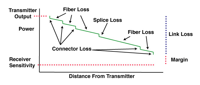
Link budget, or power budget, refers to the amount of loss that a data link (transmitter to receiver) can tolerate in order to operate properly. Sometimes it has both a maximum value and a minimum value so that the input power at the receiver end is within its operating range.
Link loss budget is the amount of loss that a cable plant should have. It is calculated by adding the losses of all the components used in the cable plant to get the estimated end-to-end loss. Obviously, the link budget and link loss budget are related. A data link will only operate properly when the link loss is within the link budget of the link.
The difference value between the power budget and the link loss budget is known as link budget buffer. The buffer value should not be too small, because the margin for error is 3 dB in a fiber link. If the in-between components are fixed, then you can save more margin by changing the transmitter or receiver on two ends; if the two end devices are fixed, you can save yourself more margin by changing the fiber optic jumpers and other passive components.
What is the fiber link budget?
The fiber link budget is the maximum signal loss allowed in the network and application. This value is calculated based on the actual network conditions and the loss specified by international standards. A complete optical fiber link includes optical fibers, connectors, and fusion splices, so when calculating the maximum loss of an optical fiber link, all these factors must be taken into account. The optical energy loss in the optical fiber communication link is composed of the loss of the optical fiber itself, the loss caused by the connector and the loss caused by the fusion splice. However, due to the uncertainty of the length of the optical fiber, the number of splices and the number of splices, the test standard of the optical fiber link is not fixed like a twisted pair. Therefore, the test standard of each optical fiber link must be calculated through calculation.
Why Does Power Budget Matter?
The purpose of power budgeting is to ensure that the optical power from the transmission side to receiver is adequate under all circumstances. As data centers migrate to 40G, 100G and possible 400G in the near future, link performance becomes increasingly essential. Link failures would stir up a sequence of problems like system downtime, which equates to accelerated costs, frustrated users, deteriorated performance and increased the total cost. While with appropriate power budgeting, a high-performance link can be achieved for better network reliability, more flexible cabling and simplified regular maintenance, which is beneficial in the long run.
What is the calculation formula for fiber link loss?
Obviously, fiber link loss is the sum of fiber attenuation, connector attenuation, splice attenuation, and system margin loss:
Optical fiber link attenuation = optical fiber attenuation + connector attenuation + splice attenuation + system margin
Fiber attenuation = fiber attenuation coefficient (dB/km) × fiber length (km);
Connector attenuation = connector attenuation/piece × number of connectors;
Attenuation of welding point = attenuation of welding point/piece × number of welding points;
The system margin includes fiber jumper, fiber optic cable bending and unpredictable optical attenuation, etc. At least 3dB margin should be left.
The average attenuation of 1310nm wavelength under normal conditions:
Optical fiber attenuation: 0.35dB/Km; optical connector: 0.6dB/piece; welding point: 0.1dB/piece.
Average attenuation of 1550nm wavelength under normal conditions:
Optical fiber attenuation: 0.2dB/Km; optical connector: 0.35dB/piece; fusion point: 0.05dB/piece.
The picture below is a typical site case:
According to the above formula, the following results can be calculated: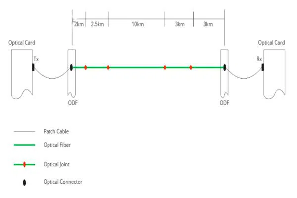
For 1310nm wavelength:
Optical fiber link attenuation = 20.5Kmx0.35dB/Km+2x0.6dB+4x0.1dB+3dB=11.78dB;
For 1550nm wavelength:
Optical fiber link attenuation = 20.5Kmx0.22dB/Km+2x0.35dB+4x0.05dB+3dB=8.41dB;
How to Calculate the Link Budget and Link Loss Before a Cable Plant?
Generally, four main parameters are used to calculate the optical transmission link budget buffer. They are minimum optical transmitter power, maximum connector insertion loss, optical fiber cable transmission loss, and maximum optical receiver sensitivity.
Transmitter power and receiver sensitivity are absolute values (e.g. mWatt or dBm, 10*log(mW) = dBm), but connector insertion loss and optical fiber cable transmission loss are relative values (e.g. % loss). The connector insertion losses comprise the connections of fiber optical jumpers, transceivers, patch panels, etc. In order to help understand how to calculate the link budget, here is an example of a typical 2-kilometer multimode link with 5 connections (2 connectors at each end and 3 connections at patch panels in the link) and one splice in the middle. The maximum fiber loss of multimode fiber is 3.5 dB/km and the maximum acceptable connector insertion loss is 0.75 dB. Typical splice loss for multimode fiber is 0.3 dB. Therefore, the total maximum link loss is 11.05 dB.
Critical Elements Involved In Calculating Power Budget
When performing power budget calculation, there are a long list of elements to account for. The basic items that determine general transmission system performance are listed here.
Fiber loss: fiber loss impacts greatly on overall system performance, which is expressed by dB per kilometer. The total fiber loss is calculated based on the distance × the loss factor (provided by manufacturer).
Connector loss: the loss of a mated pair of connectors. Multimode connectors will have losses of 0.2-0.5 dB typically. Single-mode connectors, which are factory made and fusion spliced on will have losses of 0.1-0.2 dB. Field terminated single-mode connectors may have losses as high as 0.5-1.0 dB.
Number and type of splices: Mechanical splice loss is generally in a range of 0.7 to 1.5 dB per connector. Fusion splice loss is between 0.1 and 0.5 dB per splice. Because of their limited loss factor, fusion splices are preferred.
Power margin: power budget margin generally includes aging of the fiber, aging of the transmitter and receiver components, additional devices, incidental twisting and bending of the fiber, additional splices, etc. The margin is needed to compensate for link degradation, which is within the range of 3 to 10 dB.
How to Add More Connections in the link?
If you want to add more connections in the link when the two absolute values are known, the simplest way is to choose fiber optic jumpers with low insertion loss as much as possible. Because the connector insertion loss contributes a lot to the total link loss in a fiber link. You can also use more precise splice machines but it is not as easy as using lower loss fiber optic jumpers.
Summary
Link budget and link loss budget are both vital analysis measures in fiber optic network design. The link budget is mainly used before the installation, whereas link loss budget is used before and after the installation. After the cable plant is installed, the calculated loss values are compared with the test results to ensure the link can operate properly.