What Is AWG?
If you have ever shopped for ethernet cables you'll notice that there are many difference sizes of cables. Not only can the sizes (Length) of the cables be different but the the actual cables size can be different as well. Each manufacture will produce a slightly different size of cable but there is a standard for which conductors need to be.
Wire gage sizes are a bit confusing, and we get a lot of questions about them. Why does one 12 AWG speaker cable look smaller than another? Is wire gage a good indicator of cable quality? What is wire gage, anyhow, and when and why does it matter? Let's look at these issues.In this article, we will discuss these questions about the AWG.
What Is AWG?
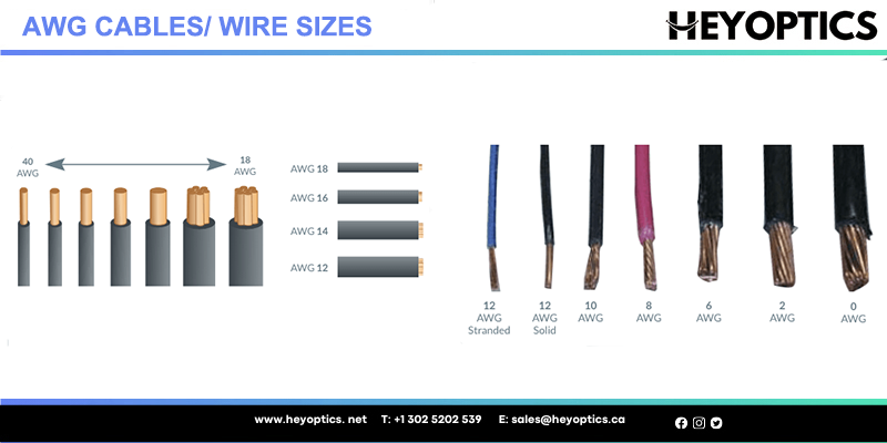
You will most likely see a AWG when looking at your ethernet cables jacket. The AWG you see stands for American Wire Gauge. AWG (American Wire Gauge) is a standardization of the sizing system of cables in North America. It provides a standard reference for comparing all types of conductor materials. This helps in guiding manufacturers to know what size of wires need to be made to meet the certain AWG size.
Wire gage is an index which shows, indirectly (inversely and logarithmically), the cross-sectional area of a round wire. In the case of solid conductors, measurement of this area is pretty straightforward: the area is the radius of the wire squared, times pi, and for the sake of ease of expression, a measure called "Circular MIL area" is instead often used instead; one circular mil is the area of a circle with a diameter of one mil (1/1000 inch), and the circular mil area of a solid wire, consequently, is always the diameter of the wire, in mils, squared.
Stranded wire is another matter. For any given AWG size, a stranded wire will occupy more space than a solid wire, because the wire gage is measured by summing the cross-sectional area of the strands. Because there are air pockets between the strands, any given cross-sectional area of wire will take up more overall space in a stranded configuration than it will in a solid wire. Consequently, when we talk about "diameter" relative to wire gage, it's well to remember that diameter will vary not only with gage but also with stranding. In this article, when we talk about relative diameters, our examples are based on solid wire for the sake of simplicity.
The relationship of gage to wire size is, for a lot of people, counterintuitive. The larger the gage number, the smaller the wire. What's more, the relationship isn't linear, but logarithmic. Two 16 AWG wires, combined, amount to a 13 AWG conductor. If you're familiar with decibels (dB), this will make good sense. If we go up or down 10 gage sizes, we increase or decrease the area of the conductor by a factor of 10. If we go up or down 3 gage sizes, we increase or decrease the area by a factor of about 2. For some reason (we're not really sure why) the relationship isn't precise, but it's close enough, for most purposes, to a straight logarithmic formula. For example, a 40 AWG solid wire has a circular mil area, as specified by the National Bureau of Standards, of 9.61; a 30 AWG wire has a circular mil area of 100.5, a 20 AWG wire comes in at 1020, and a 10 AWG at 10380.
Incidentally, it's important to remember that it is the size of the WIRE, not the size of the wire with its insulation, that is measured in AWG. On occasion, we get a call from a customer who is convinced that our 12 AWG speaker cable cannot be 12 AWG, because it looks smaller than another 12 AWG cable he owns. Many speaker cables are jacketed in a very thick translucent PVC jacket, which not only makes the overall profile bulky, but also makes for something of a magnifying-glass effect, making the wire look a bit bigger than it really is.
Understanding AWG In Ethernet Cable
The AWG is used to show the number of steps involved in the process of wire drawing. Wire drawing is a metalworking process of reducing the cross-sections of a wire by pulling the cable through a series of single or series of drawing dies. The process then goes on to create a size of the cables wires. As a result of that the AWG number and the size of the wire have an inverse relationship.
The smaller the AWG numbers means that the wire are larger. So for example a 22AWG cable has larger wires than a 28AWG cable.
The larger the AWG numbers the smaller the wires. So in reverse a 26AWG cable will have smaller wires than a 24AWG cable.
It is also worth mentioning that stranded cables generally have slightly larger outside diameters than solid conductors because of the addition of the cross sectional area between the strands. This is what helps that type of cable be more flexible.
Here's an example chart of more AWG size requirements on solid cable conductors:
| Diameter of Solid Conductors | ||
| mm | In | |
| 30 AWG | 0.251 | 0.0099 |
| 29 AWG | 0.284 | 0.0112 |
| 28 AWG | 0.318 | 0.0125 |
| 27 AWG | 0.358 | 0.0141 |
What Does Wire Gage Have to Do with a Wire's Electrical Properties?
The most significant impact of Wire Gage upon the electrical properties of a wire is upon the wire's resistance. Any given wire material (copper, steel, aluminum, et cetera) has resistance, and DC resistance is inversely proportional to the circular mil area. If our wire is copper, that 40 AWG conductor, with a 9.61 area, has a resistance of 1080 ohms per 1000 feet; the 10 AWG, with approximately 1000 times the area, has a resistance of just about exactly one ohm.
Resistance is the property of a conductor which describes how current flowing through the conductor will be converted to heat. In a very low resistance conductor, relatively little energy will be lost to heat; as resistance increases, more and more will be converted to heat.
So, AWG relates to resistance. What does Resistance Mean to Signal Quality?
What does resistance have to do with signal quality? Well, that depends very much on the application. It's commonly assumed that AWG is a good indicator of cable quality, and this assumption goes back to the earliest days of marketing of "aftermarket" speaker cable; the sales pitch which launched the whole consumer aftermarket cable business was, in essence, "bigger wire is better." And this, as we'll see, is certainly true for speaker cable (within limits), but not necessarily for other applications.
Before we get into this, a couple of preliminaries. First, it's important to remember that what we are concerned with primarily is signal quality, not amplitude. If losses in a system are not frequency-dependent, it's very easy to adjust around them; for example, typical video input circuits will simply take weak signals and amplify them to a standard reference level for use in a display. In such a case, we want to be sure that the quality of signal is clean, but it doesn't matter--at least, it matters relatively little, within reasonable limits--whether the amplitude of the signal is high or low.
Second, to understand the following discussion, it's helpful to know a bit about something called Ohm's law. The German physicist Georg Ohm discovered a simple principle about resistances which is a fundamental idea underlying all manner of electrical circuits. If a circuit contains a series of resistances--that is, if current is going to flow through one resistor, then through another, and then another--the energy of the electrical flow will be absorbed by those resistors in proportion to their resistance (which, of course, we measure in Ohms, in honor of Georg Ohm's work). You will also, probably, be familiar with another use of "ohms": impedance. Impedance is a more complicated phenomenon than resistance, and there's a lot to be said about it; but for the purposes of the following examples, we can consider ohms of impedance to be equivalent to ohms of resistance, as though impedance and resistance were exactly the same thing.
So, to illustrate Ohm's law, let's consider a speaker circuit, and we'll suppose, for the sake of this example, that the installer has decided to use a dramatically undersized speaker cable. Each conductor of this cable has a resistance of four ohms, and the speaker has an impedance of eight ohms. Signal coming from one speaker terminal and traveling to the other will go through four ohms of speaker wire resistance, through an eight-ohm speaker, and then through another four ohms of speaker wire resistance. What does this mean? The total circuit resistance is 16 ohms (to simplify matters, we're going to assume a zero ohm "output impedance"; this isn't realistic, but is good enough to illustrate the principles at work here). So, of the energy being burned up in the circuit, one quarter (4 ohms over 16 ohms) is burned up on the way from the "plus" terminal to the speaker; one half (8 ohms over 16 ohms) is delivered to the speaker; and one quarter is burned up on the other side of the speaker cable, between the speaker and the "minus" terminal of the amp.
Obviously, that's a lot of energy being burned up in speaker cable. In our discussion below, we'll explain why that's a bad thing (beyond just being a waste of electricity). But before we talk about that, let's imagine another application. Let's say that we take a cable with the same resistance properties (4 ohms out, 4 ohms back) and hook it up to RCA connectors, and use it on a line-level analog audio connection between a source device (say, a CD player) and an amplifier. An amplifier input circuit will not have a low impedance like a speaker will; 10,000 ohms, rather than 8 ohms, is somewhere around typical. Now, when we hook this circuit up, what do we find? The total circuit resistance is 10,008 ohms. Of the energy being delivered by the source, 8/10008 of it--almost nothing--is burning up in the cable, and 10000/10008 of it is being delivered to the amp. The resistance that was horribly excessive in the speaker cable, and that was consuming half the energy delivered to the circuit, is insignificant in the interconnect.
The lesson here is that one application isn't like another. Wire gage is critically important if you're delivering power from a hydro plant to a city; it's critically important if you're driving a automobile starter; it's somewhat important if you're driving a speaker; and it's practically insignificant if you're interconnecting unbalanced line-level audio. Since we're not much concerned with hydro plants and Bendix gears here, let's go down a list of common audio and video applications and talk about what relevance wire gage has to these applications.
Speaker Circuits:
In speaker cable, barring some really odd construction practices, far and away the most important aspect of a cable is wire gage. Why? Well, think back a couple of paragraphs to that Ohm's law example. That's an extreme case, admittedly, but there, half the energy of the amp is burning up in speaker wire rather than being delivered to the speaker. Now, one might think, "what's the difference? The system will be a few dB quieter, but otherwise it'll sound the same." That would be true, but for one factor we didn't consider in our example. A speaker's impedance may nominally be eight ohms, but in reality it varies with frequency, starting high at low frequencies and falling. Consider what happens to our Ohm's law example now. If at one frequency the impedance is really six ohms, and at another it's ten, Ohm's law will distribute these different frequencies differently to the circuit. Where speaker impedance is low, more of the energy is absorbed by the cable; where speaker impedance is high, more of the energy is delivered to the speaker. The result is that excessive resistance in speaker cable will cause more loss of high-frequency than low-frequency signal; the system will sound differently from one wired with adequately-sized speaker cable.
Audio Interconnects:
Audio interconnects, as we've indicated, generally operate in very high-impedance circuits. Consequently, wire gage isn't really a meaningful factor in cable quality by itself. However, wire gage may have something to do with cable quality in an indirect sense--and that indirect sense points, somewhat counterintuitively, to a smaller rather than a larger conductor being desirable.
In high impedance circuits, capacitance becomes a significant factor in cable quality; capacitance is the tendency of the cable to store up a portion of the signal in itself and release it slowly, rather than deliver it immediately to the destination. Capacitance, in a cable with a single center conductor and an outer shield, will be determined by the outer diameter of the center conductor, the inner diameter of the shield, and the type of material (dielectric) that separates them. In an unbalanced audio interconnect, there are practical limits to what one can do to the inner diameter of the shield (cable needs to be of a size that's practical to attach RCA plugs to), and to the types of material that can be used as dielectric, and so the best way, at the margin, to diminish capacitance is to reduce the AWG of the center conductor. In our LC-1 Audio Cable, that's what we've done; the center conductor is 25 AWG, which is quite small, while remaining large enough to have good flex-life (i.e., not break when flexed) and to be susceptible to a solid crimp termination. We are sometimes asked why the AWG is so small, the unstated assumption being that a larger center conductor would be better; but even in a 50-foot run, the center conductor resistance is only 1.6 ohm, a vanishingly small value compared to a typical unbalanced audio input circuit impedance.
Conclusion:
Wire gage can be a meaningful factor in cable quality; but since it is very important for some applications, like speaker wire, only moderately meaningful for others like analog and digital video, and practically meaningless for still others, it's important to understand the demands of the application before making a judgment about cable quality based upon wire gage. When manufacturers fail to publish detailed specs on products, it can be a mistake to base relative quality judgments on whatever limited specs are provided, whether those be wire gage or something else.
Using the AWG size on the cable can be a helpful reference when deciding what connectors to use such as modular RJ45 plugs. If your cable is 23 AWG you want to match up the gauge size with the same AWG connectors. So 23AWG cable will match up with 23AWG RJ45 American-made. Just make sure to also match up the correct type (Unshielded, Shielded, Solid or Stranded).
Hope this article on what is AWG was helpful. Feel free to contact us with any questions!