Insertion loss vs return loss optical fiber connector
As a crucial link of network devices interconnection, fiber optics jumper is a sort of passive optical gadget which is commonly utilized in optical interaction. Amongst them, the adapter efficiency at both ends of the jumper straight influences the optical transmission high quality.
What is insertion loss?
Insertion loss (IL) mainly refers to the dimension of the loss of light in between two set points in a fiber optics. In the field of telecommunications, insertion loss describes the loss of signal power as a result of the insertion of a tool somewhere in the transmission system, usually describes attenuation, which is made use of to reveal the ratio of result optical power as well as input optical power of the port, in dB. Obviously, the reduced the insertion loss is, the far better the insertion loss performance is. It can be understood as the loss of optical power triggered by the treatment of optical tools in optical communication system. The suggested maximum DB loss of data center fiber optics electrical wiring: the optimum is 15dB for LC multimode fiber optics adapter, 15dB for LC single-mode adapter, 20dB for MPO/ MTP multimode optical fiber adapter and 30dB for MPO/ MTP single-mode optical fiber port.

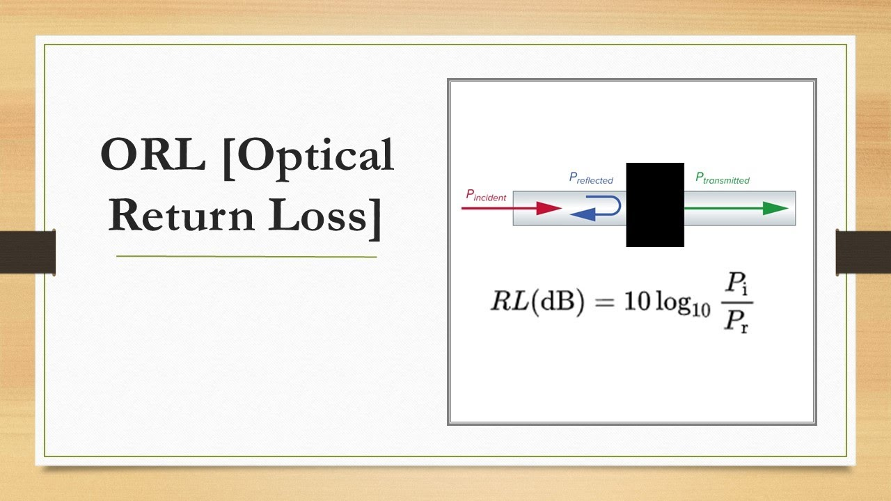
What is return loss?
When the optical fiber signal gets in or leaves an optical element (such as optical fiber adapter), the suspension as well as insusceptibility mismatch will certainly cause reflection or return. The power loss of the reflected or returned signal is called return loss (RL). The insertion loss is mainly to gauge the result signal worth when the optical web link comes across the loss, while the return loss is to measure the reflection signal loss worth when the optical link encounters the part access.
Return loss refers to the power loss triggered by the representation of some signals back to the signal resource as a result of the suspension of the transmission web link. This discontinuity may not match the terminal load or the device placed in the line. Return loss is quickly misconstrued as the loss caused by return. As a matter of fact, it describes the loss of return itself, that is, the larger the return is shed, the smaller the return is. It stands for the proportion of mirrored wave power to occurrence wave power at the transmission line port, in dB, which is usually positive. As a result, the higher the outright value of return loss, the smaller sized the amount of representation, the higher the signal power transmission, that is, the greater the RL value, the far better the efficiency of the fiber optics connector.
Elements affecting insertion loss as well as return loss
Solitary fiber optics jumper direct link is one of the most perfect fiber optics course, currently, the loss is minimal, that is, a direct connection fiber optics in between an and also B ends is not interfered. Nevertheless, in general, fiber optic networks require connectors to accomplish modularization and course splitting. As a result, the ideal efficiency of low insertion loss and high return loss will be greatly minimized as a result of the adhering to 3 factors.
1. End face quality and cleanliness
Fiber end issues (scratches, pits, splits) and particle contamination will directly impact the performance of the port, leading to greater insertion loss and also reduced return loss. Even the tiny dust fragments on the 5 micron single-mode fiber core might at some point obstruct the optical signal, resulting in signal loss. Any type of unusual situation that hinders the transmission of optical signal between fibers will certainly have unfavorable impacts on these two losses.
2. The fiber optics is damaged as well as poorly inserted
Occasionally, although the fiber has actually damaged, it can still direct light through, which will also cause inadequate IL or RL. As mentioned aware at the start of the write-up, the APC connector is gotten in touch with the PC port, one is an angle of 8 ° and the various other is the grinding angle of the mini arc surface area. Light may pass through the two adapters in a short time, but at the same time, it will certainly trigger large insertion loss as well as reduced return loss. It might likewise trigger the two optical fiber end faces can not be precisely butted, to make sure that light can not travel through usually.
3. Going beyond flexing radius
Fiber optics can be bent, but bending way too much will trigger a significant rise in optical loss, as well as might straight bring about damage. Therefore, it is recommended to keep the radius as huge as feasible when the optical fiber requires to be coiled. The general guidance is not to surpass 10 times the size of the jacket. As a result, the maximum flexing radius is 20 mm for the jumper with 2 mm outer coat.
4. Positioning and also positioning inconsistency of connector insert
The primary function of the fiber optics port is to promptly connect 2 fiber optics, make sure the accurate alignment between the two fiber cores, recognize the accurate docking of both fiber ends, and make the optical power result from the transferring fiber paired to the obtaining fiber to the maximum degree. In general, the smaller sized the diameter of the ferrule opening is, the much more main the core is. If the ferrule opening is not totally centered, the core consisted of in it will not be totally centered. As a result, the insertion loss and also return loss will be greatly affected when there is no accurate positioning in between the cores, that is, the alignment variance of the connector core.
5. End face physical contact air space
The optical fiber adapters are dealt with by adapter, which comes from physical link, however it is unreal physical call, as well as there will be void in between the contact end encounters of both adapters. The smaller the air space is, the better the insertion loss and also return loss are. The air gap between the end faces of optical fiber ports modifications with different grinding techniques. In general, the normal insertion loss of fiber optics port with physical contact (PC), ultra physical end face (UPC) and also inclined physical get in touch with (APC) grinding is less than 0.3 dB. Among them, the UPC port has the lowest insertion loss because of the minimal air space, while the APC adapter has the greatest return loss because of the inclined fiber end. Choosing the appropriate type of fiber adapter can assist you achieve better optical transmission high quality.
How to enhance the loss of optical fiber adapter?
Making use of proper high-grade fiber optics ports contributes to the long-term stable operation of high-speed transmission system. Below are some tips to help optimize the insertion loss and return loss:
● Make sure the optical fiber port is tidy prior to usage. If infected, tidy with suitable devices.
● When making use of, prevent using any kind of improper pressure on the optical fiber, and also do not bend the optical fiber past its maximum flexing distance.
● Bending, coiling, welding as well as combining of optical fiber jumpers must be stayed clear of as much as feasible, or else the optical signal might be refracted when going through the optical fiber cladding. If the fiber optics needs to be curled, a big coil radius ought to be kept.
● Usage factory ended fiber. These discontinuations are executed under rigorous control and are typically assured by the supplier.
● Sensible equilibrium in between power loss and fiber expense, making use of low-cost and also substandard fiber may cause higher price loss in the future.
Use factory terminated fiber. These terminations are accomplished under stringent control and also are typically guaranteed by the producer. Reasonable balance in between power loss and also fiber cost, using low-cost and inferior fiber might create better expense loss in the future.
Integrating the insertion loss and also return loss 2 essential optical indexes, we can much more properly evaluate the transmission performance and also performance of optical fiber, as well as judge whether there is insusceptibility mismatch in the pins of receiver and also transmitter, in addition to with openings, adapters and also various other gaps. Comprehending the insertion loss and return loss of fiber optics port will certainly help you to deploy a much better optical transmission network.