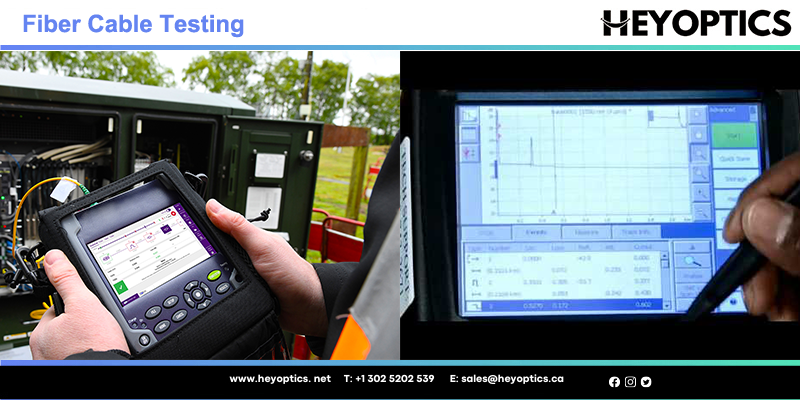
How to Test Fiber Optic Cables?
As the ever-increasing popularity of intensive bandwidth applications, the demand for fiber optic installations and infrastructures has accelerated parallelly. Optical fiber cable thus has possessed a rather essential position in the telecom industry. Consequently, the optical fiber cable testing also matters much as the final procedure of the optical network cabling. But how to deliver valid optical fiber cable testing?This article introduces you to the method of Fiber Cable Testing.
What Is Fiber Testing?
Fiber testing encompasses the processes, tools, and standards used to test fiber optic components, fiber links, and deployed fiber networks. This includes optical and mechanical testing of discreet elements and comprehensive transmission tests to verify the integrity of complete fiber network installations.
Fiber optics have emerged as the world’s leading communication transport medium. The increasing diversity of fiber optic applications has highlighted the need for technician training and versatile, user-friendly test solutions.
Why Fiber Cable Testing Matters
Proper testing of fiber optic cables can extend system life, minimize system downtime, reduce maintenance requirements, and support system upgrades and reconfigurations. All of these features can significantly improve your network performance, reliability, and manageability in the long run.
Optical Fiber Cable Testing Methods
Fiber optic cable is tested to ensure continuity and attenuation. Basically, there are three methods commonly performed for optical fiber testing: visible light source, power meter and light source (one jumper method), and optical time domain reflectometer (OTDR).
Visible Light Source Testing
Visible light source tests optical fiber continuity. Optical fiber communication systems operate in the infrared region of the electromagnetic spectrum which is invisible to the human eye. However, (red) visible light sources are available for testing and troubleshooting optical fiber systems. They are also referred to as visual fault locators and visual fault finders.
When performing fiber cable testing with a visible light source, you could follow the suggested procedures:
- Connect the optical fiber flashlight to one end of a fiber strand (with most units, the fiber must be terminated).
- Look at the opposite end. (Notice: Be careful not to look directly at active optical fiber strands. Laser light sources can cause serious eye damage.)
- If the light is not visible at the opposite end, a break or other problem is likely to present somewhere along the length of the fiber. In many instances, the fault location will glow red from the light of the visible light source.
- Document the test result information.
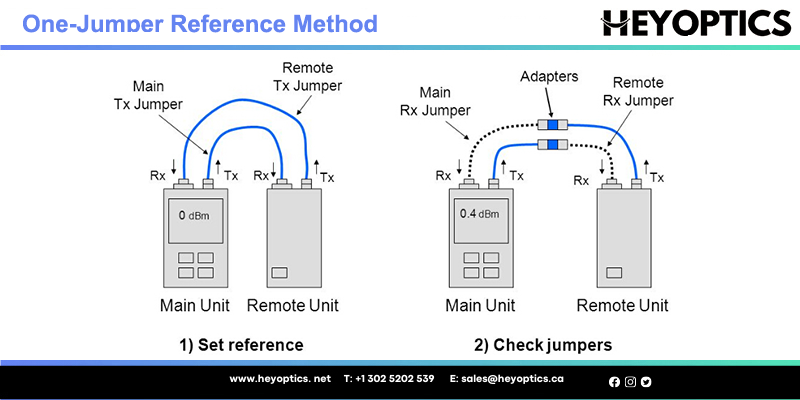
Power Meter and Light Source Testing
Power meter and light source testing are also called the one jumper method. It is the most accurate way to measure the end-to-end signal loss of the fiber, namely attenuation. Listed below are TIA/EIA- 568 insertion loss limits for the various components. Specific installations or protocols call for stricter limits.
Loss budget (TIA/EIA specification limits)
| Element | Insertion Loss |
| Splice | < 0.3 dB at all wavelengths |
| Connector Pair | < 0.75 dB at all wavelengths |
Test results should be compared with the link attenuation allowance calculated as follows:
Link Attenuation Allowance (dB) = Cable Attenuation Allowance (dB) + Connector Insertion Loss Allowance (dB) + Splice Insertion Loss Allowance (dB)
When testing optical fiber cable with a power meter and light source, the following steps need to be done.
- Disconnect active equipment.
- Acquire suitable light source for the single mode (generally 1310 nm or 1550 nm), multimode (850 nm or 1300 nm), and power meter.
- Verify proper wavelength to set source and meter. (Note: Calibration of the equipment is required before each test. Follow the equipment manufacturer’s procedures.)
- Acquire accurate test jumpers and couplers, which should be part of the light source and power meter kit.
- Connect the jumper (containing the same fiber size as the system fiber) to the optical source and the optical power meter. Turn unit on. Record the reference power reading (Pref), displayed in dBm.
- By applying an adapter, insert a second jumper (Test jumper 2) between the jumper used in Step 5 and the optical power meter. Verify the attenuation added by the second jumper is not greater than 0.75 dB: Pref-Pcheck ≤ 0.75 dB.
- Attach the jumpers to the optical source and optical power meter. Firstly, disconnect the two jumpers at the adapter. Then, connect the optical source/Test jumper 1 to one end of the system fiber to be tested. Next, connect the optical power meter/Test jumper 2 to the other end of the system fiber. After that, document the test power (Ptest) and subtract the test power (Ptest) from the reference power (Pref) recorded in Step 5. Finally, conclude the end-to-end attenuation: Attenuation (dB) = Pref-Ptest.
- Document the test results.
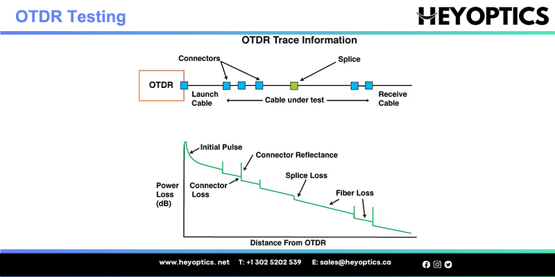
Optical Time Domain Reflectometer (OTDR) Testing
Optical time domain reflectometer (OTDR) measures the fiber cable length, attenuation, and “events” along the length of the fiber. Here, the events can be splices, breaks, or stress points that cause excessive attenuation. The OTDR does this by sending light pulses down the cable and measuring the timing and power of light reflected back to the OTDR by the events and the fiber itself. It uses this information to display a “trace”, which is a graph of power versus distance.
An OTDR only requires access to one end of a fiber for regular fiber cable testing. Because an OTDR is an indirect measurement method, it is not as accurate as a light source and power meter for measuring attenuation. However, due to its ability to display a graph of the fiber, it is particularly useful in troubleshooting. Like a power meter and light source, an OTDR tests at specific wavelengths (generally 1310 nm and/or 1550 nm for single mode and 850 nm or 1300 nm for multimode).
Conclusion
With the scale and complexity of today's fiber optic networks, productivity is no longer an option. Efficiency must start in the laboratory and continue throughout construction and maintenance. Capturing the correct test methodology plays a vital role in testing the accuracy of legacy and future systems. Of the three fiber optic cable testing methods mentioned in this article, which method to choose depends on your specific needs and actual situation. Hopefully what we discussed above can help you provide better fiber optic cable testing.