How to Terminate with an RJ45 Connector
Have you ever noticed the copper cable plugged into your computer? Or to put it specifically, the crystal connector in your computer? That’s what we called RJ45 connector. The use of modular electronic connectors has been one factor in the explosion of communication and data services around the world. One of the most widely used types in the modular family of devices is the RJ45 connector. What is an RJ45 connector? It’s a common component used to connect computers to Ethernet-based local area networks (LAN). But how much do you know about this simple connector? Let’s get together to make sense of what it looks like and how to terminate the Ethernet cable with it.
What is an RJ45 Connector?
An RJ45 connector is a commonly used modular interconnection device matched with a cable to provide data communication service to various electronic devices and systems.
The various connectors developed using this system were categorized by the FCC in 1976 into the Registered Jack (RJ) system, giving rise to the RJ label. This was done to ensure compatibility between phone company hardware and consumer equipment. The RJ system covers the physical connector, wiring patterns, and signal specifics.
RJ45 devices, like all modular connectors, contain metal contacts separated by insulating plastic channels. The channels fit into a matching socket and the connectors lock in place with a tab making them secure but also removable. Internally, RJ45 devices contain 8 pins and 8 wire positions used to handle signals or power, so they can accommodate 4 twisted wire pairs. Several other types of connectors closely resemble RJ45, and someone may easily feel confused about them. For example, the RJ11 connector used with telephone cables is one such connector. But this connector only uses six positions rather than eight positions, which makes them less popular than RJ45 connectors.
Color Coding Diagram of RJ45 Connector
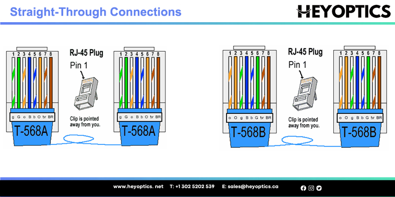
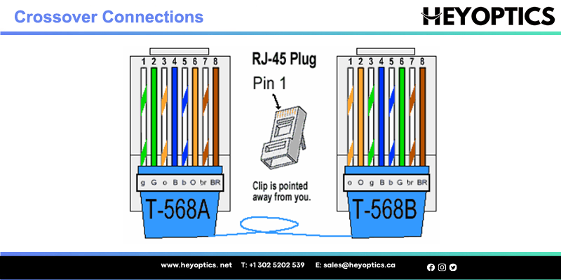
As we all know, when connecting an RJ45 connector to a cable, two wiring standards define how the RJ45 pinout arranges the individual eight wires - T568A and T568B. For both standards, there are two different forms of connection. If both ends of the jumper are routed to one standard, it is a straight-through connection. If not, it is a cross-connect. Both standards can be used for straight-through cables. Here is a color-coded illustration of the RJ45 connector when deployed in different connections.
Straight-Through Connections
No matter with the standard T-568A or T-568B, once the color order on one end is defined, so does the other end, which means the color order is the same on both ends. Take T568A straight through connection for example. The color order of one modular plug is green/white, green, orange/white, blue, blue/white, orange, brown/white, and brown. The color order of another modular plug must be corresponding with it.
Crossover Connections
This connection is different from the straight through one, for the color order is different on both ends. It’s no need to spend time remembering how many color orders there may be in this connection. Because you can get a crossover connection by wiring one end using T-568A standard and the other end using T-568B standard. Just like the following picture shows. Or remembering the color coding by simply switching the green set of wires in place with the orange set of wires. Put it in simple terms, switch the green (G) with the orange (O), and switch the green/white with the orange/white.
RJ45 Features and Capabilities
RJ45 connectors incorporate the basic features of modular connectors: low cost, solderless assembly of connector and wiring, quick production of custom cables, simple insertion and removal, easy field assembly with simple tooling, and the ability to customize cables on-site. Sockets (or receptacles) can also have a vertical or horizontal orientation, allowing their use in various applications. Beyond this, RJ45 connectors also feature the aforementioned orientation tab to prevent incorrect wiring. Their 8-pin configuration also means that they can be used in more demanding and data-intensive applications.
Additional available features can include:
- Shielding - to cancel the effects of EMI/RFI
- Keying - to ensure proper insertion
- Various mounting capabilities - to allow for panel, board, surface or through hole methods
- Displays and indicators - to indicate connection status
- Integrated magnetics - to allow for better shielding plus current protection
- Hi-Rel - to provide protection for the hardware and the connection
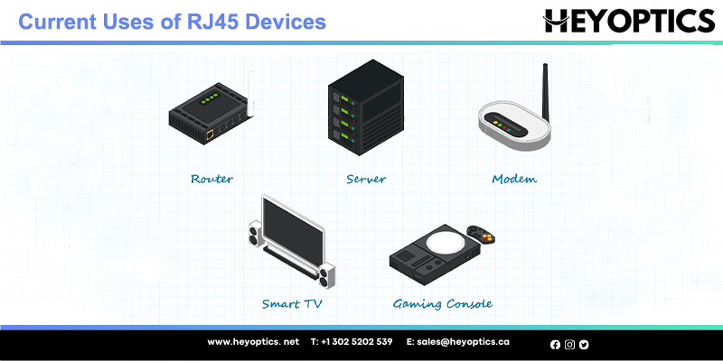
Current Uses of RJ45 Devices
RJ45 devices are chiefly used to connect an internet-enabled device (such as a PC) with another network device such as a server, router, modem, smart TV, gaming console, and other devices that use the Ethernet protocol. Ethernet networks are common in both professional and domestic environments. Hardwiring using RJ45 devices enables higher data speeds with stability and security of data transfer, making them also attractive for use in industry and on the factory floor.
RJ45 and Ethernet
Ethernet is simply a way of connecting computers and other devices within a physical space. It enables the transmission of data over a Local Area Network (LAN) or Wide Area Network (WAN) and connects them via cable allowing them to communicate with each other.
The Ethernet standard (IEEE 802.3) was developed by the Institute of Electrical and Electronic Engineers (IEEE) in the 1980s and is presently the most popular LAN technology in use worldwide. It defines the rules for configuring an Ethernet network (connections), the number of conductors that are required for a connection, the expected performance, and a framework for data transmission.
The wide acceptance of Ethernet technology is due to the balance it offers between ease of installation, speed, cost, and broad network protocol support. RJ45 connectors are the standard devices used in network set-up.
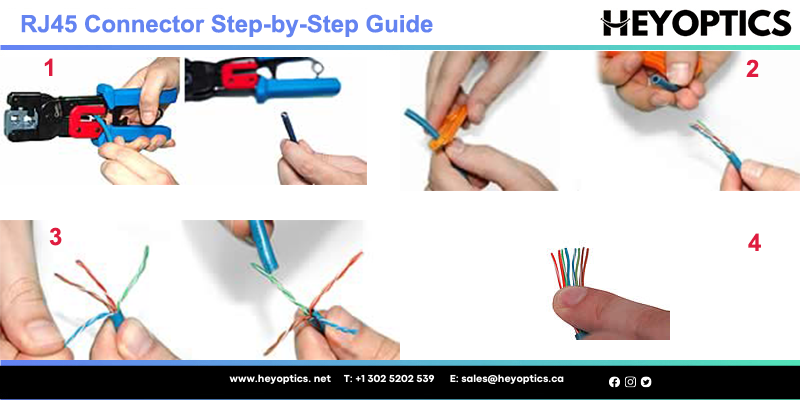
Simple Guidance to Terminate Ethernet Cable With RJ45 Connector
If you are installing or maintaining a local area network (LAN), one of the most important things you need to know is how to terminate Cat5, Cat5e or Cat6 network cables with RJ45 connectors. Mastering this skill can sometimes save time and money in Ethernet cable installation. Count on our step-by-step guides to take you through your project.
- Using a Crimping Tool, trim the end of the cable you're terminating, to ensure that the ends of the conducting wires are even.
- Being careful not to damage the inner conducting wires, strip off approximately 1 inch of the cable's jacket, using a modular crimping tool or a UTP cable stripper.
- Separate the 4 twisted wire pairs from each other, and then unwind each pair, so that you end up with 8 individual wires. Flatten the wires out as much as possible, since they'll need to be very straight for proper insertion into the connector.
- Holding the cable with the wire ends facing away from you. Moving from left to right, arrange the wires in a flat, side-by-side ribbon formation, placing them in the following order: white/orange, solid orange, white/green, solid blue, white/blue, solid green, white/brown, solid brown.
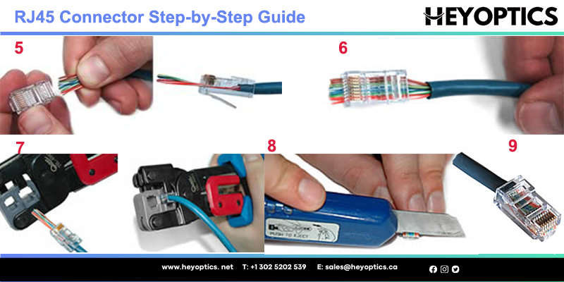
- Holding the RJ45 connector so that its pins are facing away from you and the plug-clip side is facing down, carefully insert the flattened, arranged wires into the connector, pushing through until the wire ends emerge from the pins. For strength of connection, also push as much of the cable jacket as possible into the connector.
- Check to make sure that the wire ends coming out of the connector's pin side are in the correct order; if not, remove them from the connector, rearrange into proper formation, and re-insert. Remember, once the connector is crimped onto the cable, it's permanent. If you realize that a mistake has been made in wire order after termination, you'll have to cut the connector off and start all over again!
- Insert the prepared connector/cable assembly into the RJ45 slot in your crimping tool. Firmly squeeze the crimper's handles together until you can't go any further. Release the handles and repeat this step to ensure a proper crimp.
- If your crimper doesn't automatically trim the wire ends upon termination, carefully cut wire ends to make them as flush with the connector's surface as possible. The closer the wire ends are trimmed, the better your final plug-in connection will be.
- After the first termination is complete, repeat process on the opposite end of your cable
Conclusion
This article covers the basics of RJ45 in different connections and how to use it to terminate Ethernet cables. The RJ45 connector is a key part of an Ethernet connection for transporting voice and data media. They were developed as a smaller, less expensive alternative to hard wiring for older telephone installation methods. Simple plug-and-play style reduces installation difficulty.
Like other modular connectors, RJ45 devices offer simple design, quick and easy installation, wide product and user accessibility. Since Ethernet systems provide a flexible and efficient way to transmit voice and data media, RJ45 connectors serve as A key part of Ethernet connectivity, it is becoming more and more popular. Therefore, it is beneficial to have knowledge about it.
They are accepted globally for home and office networking applications and are increasingly being accepted on factory floors and harsh environments.