Fiber Polarity Method: How to Choose?
40G and 100G are now universally deployed in data centers. As the preferred array-based fiber connector option, the MPO/MTP connector and its cable assemblies are widely used for 40/100G connectivity in high-density data center environments. It's proved that MTP/MPO system is the answer to solving cable congestion in data centers or enterprises because it featured flexibility, reliability, and scalability. However, the network designers face another challenge how to assure the proper polarity of these array connections using multi-fiber MTP/MPO components from end to end.
Maintaining the correct polarity across a fiber network ensures that a transmit signal from any type of active equipment will be directed to receive port thef the second piece of active equipment – and vice versa. However, in complex high-density cabling, the advantages of MPO/MTP cabling will be lost if you don’t have a proper polarity method. To ensure the MTP/MPO systems work with correct polarity, the TIA 568 standard provided three methods, which will be introduced in this article.
MTP/MPO Connector and MTP/MPO Polarity
The MTP/MPO connector is a multi-innovative, high-performance fiber optic connector that has enhanced optical and mechanical performance. The special design (shown in the following figure) of the MTP/MPO connector ensures the accuracy of the polarity in the MTP/MPO network system.
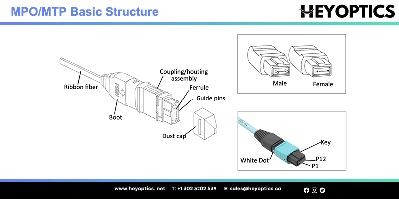
Before looking at each method in detail, it is necessary to understand the basic structure of an MPO/MTP connector. As the following picture shows, an MPO/MTP connector contains several parts such as a boot, coupling/housing assembly, ferrule, guide pins, and so on. When the MPO/MTP connector is designed with pins, it is called a male connector. On the contrary, it is called the female connector.
In addition, there is a “key” on one side of the connector body. When the key sits on top, we call that it is the key-up position. In this orientation, each of the fiber holes in the connector is numbered in sequence from left to right. We will refer to these connector holes as positions, or P1, P2, etc. Generally, there is a marker called a “white dot” on the side of the connector body that is used to designate the position on 1 side of the connector when it is plugged in.
What is polarity?
A general optical link requires two optical fibers to complete the entire transmission process. For example, the optical module has a receiving end (Rx) and a transmitting end (TX). When in use, it is necessary to ensure that the receiving end and the transmitting end are in an interconnected state, and such matching between the transmitting end and the receiving end at both ends of the optical link is known as polarity. In common cabling systems, connectors such as LC and SC can easily be matched, so there is no polarity issue. However, for pre-terminated, high-density MTP/MPO cabling systems, polarity issues must be addressed.
Polarity Method Introduction
The TIA-568-C.0 standard illustrated three array system connectivity methods—Method A, Metho,d B, and Method C. This section will introduce them.
Method A
As shown in the picture below, two Method A cassettes with key-up to key-down adapters, a straight-through key-up to key-down MPO trunk cable as well as two patch cables are required in Method A connectivity. The straight-through key-up to key-down MPO trunk cable means that the fiber 1 located in P1 of the connector on the left will arrive at P1 at the other connector. What’s more, it should be noted that the transmit‐receive flip must happen in the patch cables for Method A. In other words, an “A-to-A” patch cable is at one end of the connection while an “A-to-B” patch cable is at the other end.
Method B
In Method B, as shown in the following picture, Method B cassettes that employ key-up to key-up adapters are required to link straight-through key-up to key-up MPO trunk cable. With the key up on both ends, the key-up to key-up trunk cable has a different fiber array with Method A type cable. In this type of trunk cable, fiber 1 (Tx) is mated with fiber 12 (Rx), fiber 2 (Rx) is mated with fiber 11 (Tx), and so on. Two straight “A-to-B” patch cables are required at the beginning and end of the link, namely patch cables do not need to be flipped in Method B.
Method C
Method C uses the same cassettes as Method A, linking a special key-up to key-down trunk cable. For Method C, each adjacent pair of fibers at one end are flipped at the other end. Notice the swapping of the color positions in the picture below. The fiber channel is completed by utilizing straight “A-to-B” patch cables at the beginning and end of the link. Method C is similar to Method A. The only difference between this method and Method A is that the pair-wise flip occurs in the array cable itself rather than at the patch cables so that odd-numbered Tx fibers leaving the near-end cassette are in even-numbered Rx positions when they arrive at the remote cassette, e.g. fiber 1 (Tx) is mated with fiber 2 (Rx).
Three Cables for Three Polarization Methods
The three methods for proper polarity defined by TIA 568 standard are named Method A, Method B, and Method C. To match these standards, three types of MTP fibers with different structures named Type A, Type B, and Type C are being used for the three different connectivity methods respectively. In this part, the three different cables will be introduced firstly, and then the three connectivity methods.
MTP Trunk Cable Type A: Type A cable, also known as straight cable, is a straight through cable with a key up MTP connector on one end and a key down MTP connector on the opposite end. This makes the fibers at each end of the cable have the same fiber position. For example, the fiber located at position 1 (P1) of the connector on one side will arrive at P1 at the other connector. The fiber sequence of a 12 fiber MTP Type-A cable is shown as the following:
MTP Trunk Cable Type B: Type B cable (reversed cable) uses a key up the connector on both ends of the cable. This type of array mating results in an inversion, which means the fiber positions are reversed at each end. The fiber at P1 at one end is mated with fiber at P12 at the opposing end. The following picture shows the fiber sequences of a 12 fiber Type B cable.
MTP Trunk Cable Type C: Type C cable (pairs flipped cable) looks like Type A cable with one key up connector and one key down connector on each side. However, in Type C each adjacent pair of fibers at one end are flipped at the other end. For example, the fiber at position 1 on one end is shifted to position 2 at the other end of the cable. The fiber at position 2 at one end is shifted to position 1 at the opposite end etc. The fiber sequence of Type C cable is demonstrated in the following picture.
How to Choose?
The above section shows us the details of these three methods. The following table summarizes the advantages and disadvantages of them which may guide you to choose a proper one for your network. But, it is very important to know that the method choice should be maintained consistently throughout the installation. Do not mix them throughout the installations.
| Method | Pros | Cons |
| A | One cassette type, easy to produce and purchase Compatible with many legacy systems Multiple sources for components Industry standard Single-mode and multimode Standard provides migration path to parallel optics Ribbon cables can be linked (need male/female connector) |
Requires pre-configured “A-to-A” patch cables, or field configuration of same |
| B | Single source for components | Remote cassette must be flipped and re-labeled |
| “A-to-B” patch cable only | Identification and maintenance of cassettes are different on each end | |
| Industry standard | Multimode only | |
| Standard provides migration path to parallel optics | Not compatible with legacy systems | |
| Ribbon cables can only be liked using less available (Key Up to Key Up) adapters (need male/female cable) | ||
| Fewest vendors | ||
| C | One cassette type, easy to produce and purchase | Less reliable than Method A |
| Singlemode and multimode | Specialized ribbon cable assembly | |
| Industry standard | Does not support parallel optics | |
| “A-to-B” patch cable only | Not compatible with legacy systems | |
| Less vendor support than Method A | ||
| Difficult to extend link |
Keep MTP/MPO Polarity Rules When Building Connection
When fiber patch cords have different polarity schemes and gender, IT staff needs to be very careful when replacing patch cords in the field. Those who don’t understand polarity or are in a rush to get equipment up and running can potentially use the wrong patch cord and impact signal transmission.
Rules for MTP/MPO Cable and Patch Cable Connection
Where there are A-to-A type patch cable and A-to-B type patch cable, there are three general types of array (multi-fiber) cable assemblies. It is noted that the alignment pins on the MTP/MPO connectors are important for maintaining the correct polarity. Therefore, it is necessary to make sure of proper pin position before you connect MTP/MPO fiber with patch cable.
A-to-B type LC/SC duplex patch cable is the standard crossover cord that maps the Tx port to the Rx port. With the flip, A-to-B type patch cable maintains proper polarity. And MTP trunk cable Type B reverses the fiber positions at each end (1 to 12 and 12 to 1) and the connector keys are both oriented face up. This kind of cable connection is recommended to keep proper MTP/MPO polarity.
Rules for MTP/MPO Cable and Cassette Connection
The selection of the MTP/MPO cassette will also determine the choice of the MTP/MPO cable. You’d better choose a cassette with proper alignment pins so that MTP/MPO cassettes can near perfect mate with the MTP/MPO connectors at either end of MTP/MPO cables. In addition, the rear of the adapter mounted on the cassette defines it as either Method A or Method B to correspond with the TIA standard.
Conclusion
This post introduced three array system connectivity methods and listed their pros and cons that may guide you for polarity selection. In a word, Method A is polarity flip in the A‐to‐A patch cord. Method B is polarity flip in the cassette. And Method C is flipped by pairs.
Network designers use MTP/MPO components to satisfy the increasing requirement for higher transmission speed, during which one of the big problems—polarity, can be solved by selecting the right types of MTP cables, MTP connectors, MTP cassette, and fiber optic cables. The three different polarization methods can be applied according to the satisfy requirements in different situations.